?2008 Fairchild Semiconductor Corporation
www.fairchildsemi.com
FAN9611 " Rev. 1.1.7
15
9. Input Voltage Sensing (V
IN
)
The input AC voltage is sensed at the VIN pin. The input
voltage is used in two functions: input under-voltage
lockout (brownout protection), and input voltage
feedforward in the PWM control circuit. All the functions
require the RMS value of the input voltage waveform.
Since the RMS value of the AC input voltage is directly
proportional to its peak, it is sufficient to find the peak
instead of the more complicated and slower method of
integrating the input voltage over a half line cycle. The
internal circuit of the VIN pin works with peak detection
of the input AC waveforms. One of the important
benefits of this approach is that the peak indicates the
correct RMS value even at no load when the HF filter
capacitor at the input side of the boost converter is not
discharged around the zero crossing of the line
waveform. Another notable benefit is that during line
transients, when the peak exceeds the previously
measured value, the input-voltage feedforward circuit
can react immediately, without waiting for a valid
integral value at the end of the half line period.
Furthermore, lack of zero crossing detection could fool
the integrator while the peak detector works properly
during light-load operation.
The valid range for the peak of the AC input is between
approximately 0.925 V and 3.7 V. This range is
optimized for universal input voltage range of operation.
If the peak of the sense voltage remains below the
0.925 V threshold, input under-voltage or brownout
condition is declared and the FAN9611 stops operating.
When the V
IN
voltage exceeds 3.7 V, the FAN9611 input
voltage sense circuit saturates and the feedforward
circuit is not able to follow the input any higher.
Consequently, the slope of the PWM ramp remains
constant corresponding to the V
IN
= 3.7 V level
amplitude for any V
IN
voltage above 3.7 V.
The input voltage is measured by a tracking analog-to-
digital converter, which keeps the highest value (peak
voltage) of the input voltage waveform. Once a
measurement is taken, the converter tracks the input for
at least 12 ms before a new value is taken. This delay
ensures at least one new peak value is captured before
the new value is used.
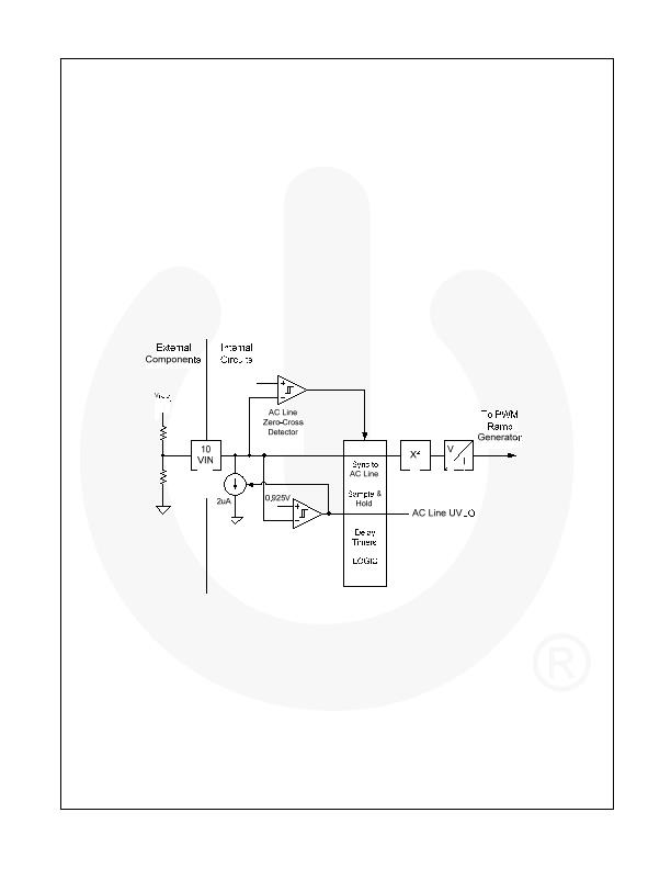
Figure 23. Input Voltage Sensing Circuit
The measured peak value is then used in the following
half-line cycle while a new measurement is executed to
be used in the next half line cycle. This operation is
synchronized to the zero crossing of the line waveform.
Since the input voltage measurement is held steady
during the line half periods, this technique does not feed
any AC ripple into the control loop. If line zero crossing
detection is missing, the FAN9611 measures the input
voltage in every 32 ms; it can operate from a DC input
as well. The following figures provide detail about the
input voltage sensing method of the controller.
As shown in the waveforms, input voltage feedforward is
instantaneous when the line voltage increases and has
a half line cycle delay when the input voltage decreases.
Any increase in input voltage would cause output over
voltage due to the slow nature of the voltage regulation
loop. This is successfully mitigated by the immediate
action of the input-voltage feedforward circuit.
发布紧急采购,3分钟左右您将得到回复。
相关PDF资料
FAN9612MX
IC CTLR PFC DUAL BCM 16SOICN
FL6961MY
IC CTLR PFC SGL FLYBACK 8-SOIC
IR1150ISTRPBF
IC PFC CONTROLLER CCM 8-SOIC
IR1152STRPBF
IC PFC ONE CYCLE CONTROL 8SOIC
IR1153STRPBF
IC PFC ONE CYCLE CONTROL 8SOIC
IR1155STRPBF
IC PFC ONE CYCLE CONTROL 8SOIC
IRS2500SPBF
IC PFC
IRS2548DSPBF
IC PFC
相关代理商/技术参数
FAN9612
制造商:Fairchild 功能描述:INTERLEAVED PFC IC
FAN9612M
制造商:Fairchild Semiconductor Corporation 功能描述:
FAN9612MX
功能描述:功率因数校正 IC Interleaved Dual BCM PFC Controller RoHS:否 制造商:Fairchild Semiconductor 开关频率:300 KHz 最大功率耗散: 最大工作温度:+ 125 C 安装风格:SMD/SMT 封装 / 箱体:SOIC-8 封装:Reel
FAN9612Y FAN9613Y WAF
制造商:Fairchild Semiconductor Corporation 功能描述:
FAN9613_YAC3026B WAF
制造商:Fairchild Semiconductor Corporation 功能描述:
FAN9621
制造商:FAIRCHILD 制造商全称:Fairchild Semiconductor 功能描述:Interleaved Dual BCM PFC Controller
FAN-AC3
制造商:Cosel Usa Inc 功能描述:Optional Accessories, OP Series
FAN-AC3-F
制造商:Cosel Usa Inc 功能描述:Optional Accessories, OP Series
